homemade tin foil guitar effects

Experiment with diodes. placed them back to back and connected the one end to base of transistor and the other to ground. Its supposed to add distortion, from what I can tell it takes it away. same circuit as before just with the diodes.
 

Attachments

  • VID_20251014_113805~2.mp4
    16.4 MB
Last edited:
Hi Trevor, I don't know if you care about this but if you want clean sound you have to bias the transistor. It has to be operating in its linear range.

First of all, what kind of transistor is it?

Your batteries look like 6 volts, is that right?

So you can just swag the bias, call it 3 volts, which is a convenient half of 6. 3 volts is available between your battery packs. Put 3 volts on the base of the transistor and see what happens.

You want the capacitor connected to the base of the transistor and the inductor connected to ground.

In the emitter follower circuit you're using, there is no gain. It won't amplify, won't make the signal any louder. The purpose of biasing the transistor is to clean up the input, so at least the sound coming out of your little speaker should be clear if not loud.

Here's a fun experiment: see if you can make the LED turn on when the music plays.
 
Here, this should be right up your alley.

The Component Abuse Challenge.

Can you turn your LED into a light dependent capacitor?

 
First of all, what kind of transistor is it?
NPN

So you can just swag the bias, call it 3 volts, which is a convenient half of 6. 3 volts is available between your battery packs. Put 3 volts on the base of the transistor and see what happens.

You want the capacitor connected to the base of the transistor and the inductor connected to ground.

In the emitter follower circuit you're using, there is no gain. It won't amplify, won't make the signal any louder. The purpose of biasing the transistor is to clean up the input, so at least the sound coming out of your little speaker should be clear if not loud.

Here's a fun experiment: see if you can make the LED turn on when the music plays.
I was told to connect the inductor and capacitor to the base of the transistor and the collector, but was also told that part of the output needs to circle around to the input. The base is the input to the transistor but it seems like the emitter is the output? the collector is also an input, so does attaching two inputs create a loop?
 
This circuit I tie the output of the transistor which is P NP and the base of the transistor with a capacitor and an inductor
 

Attachments

  • VID_20251017_122430~2.mp4
    13.8 MB

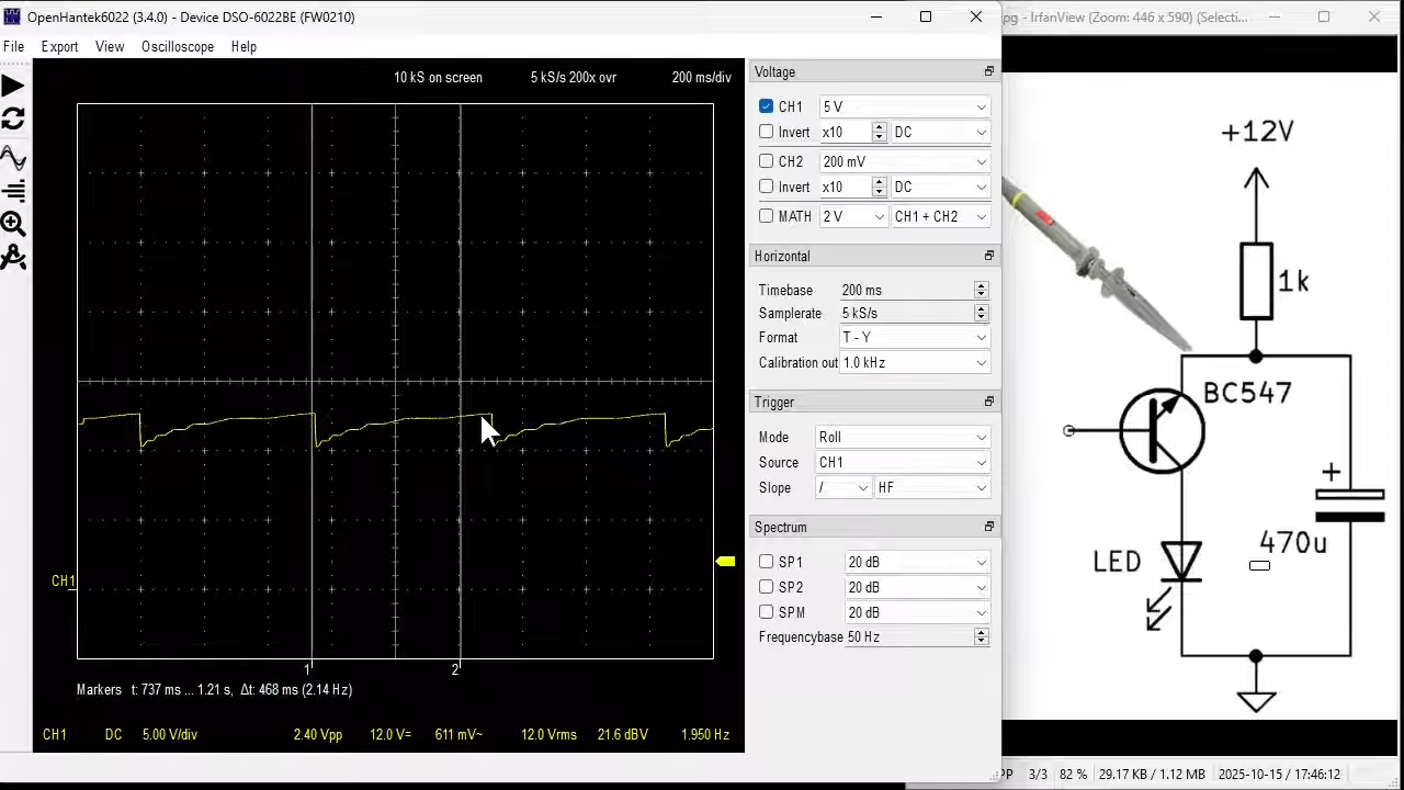
For an NPN transistor, the collector wants to be positive. So you connect the + side of your battery to the collector, and the - side to the emitter. There are usually resistors on both sides, between the transistor and the battery. The curves in this pic show how the transistor operates. Vce is your collector to emitter voltage, which is your battery. Ic is the collector current.

1760722157245.webp


The idea of the transistor is, the base current is very small, and it regulates the much larger current from emitter to collector. Essentially the base is acting as a "gate" for the current between the emitter and the collector.

In the pic, you can see the values of base current (Ib), and the operating behavior of each curve.

The point Q is where you want to set your bias ("quiescent operating point") so there is plenty of headroom in any direction and so the transistor is sitting more or less in the middle of its linear operating range. When that is the case, a tiny change in base current will bring about a much larger change in collector current, therefore your transistor will "amplify" any signal arriving at its base.

This link describes some of the ways of biasing an NPN transistor. The idea is, you put a small positive voltage on the base, and a larger positive voltage on the collector.


I was told to connect the inductor and capacitor to the base of the transistor and the collector, but was also told that part of the output needs to circle around to the input. The base is the input to the transistor but it seems like the emitter is the output? the collector is also an input, so does attaching two inputs create a loop?

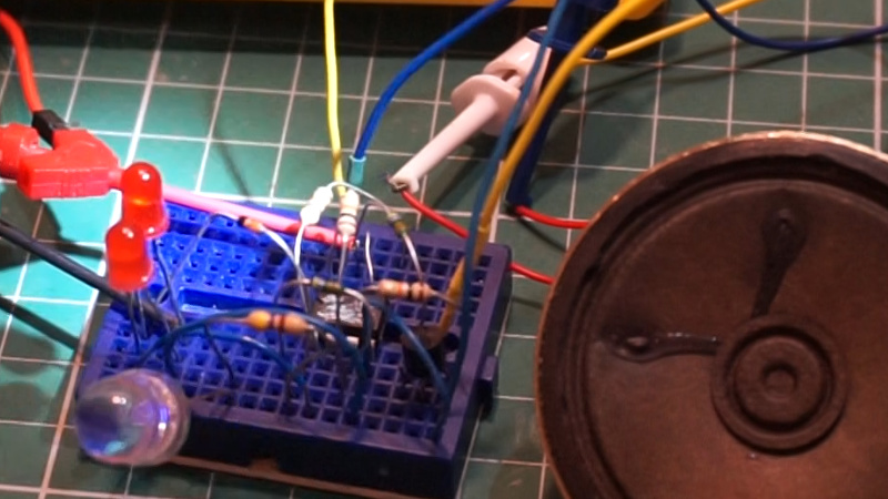
Your output (speaker connection) can come from any point in the circuit where there is a changing signal. You must isolate your speaker from DC, there can be no DC allowed in the load. There are two ways of doing this: 1) you can "inline" the load in either the collector leg or the emitter leg of your circuit (that's how you're doing it, you're inlining the little red speaker in the emitter leg), or 2) you can isolate your speaker from DC with either a capacitor or a transformer, and connect it in parallel with any of the load resistors.

An emitter follower (your circuit) is also called a "common collector" circuit). That means you connect the commons (grounds) of both your input and output to the collector side rather than the emitter side. This is why you were told to connect your input between base "and collector". Both ways are possible, in fact common-emitter is way more prevalent in the real world. The need is your output voltage has to be relative to "something", it could be relative to the emitter which is 0v or it could be relative to the collector which is 6v. In the latter case your input signal will be "phase inverted" because you're subtracting your original signal from a fixed value.

You can think of a gigantic water pipe where the water flows from emitter to collector (that's your "current"), then your base is like the control valve that turns your current on and off. For your output you want to access the current, and you can do that either at the emitter or at the collector.
 
no the signal placed directly on the little red speaker is louder then the setup in the video. I also tried re-building the circuit different and the same with mixed results. If the music was loud, the inductor nail had no effect, if it was quiet and crackly the nail had more influence. So, and its really easy to rip apart and test new circuits with the snap circuits, I see the diagrams and pictures of wiring and wonder, having never worked with anything other then snap circuits, if that isn't an advantage to be able to re assemble like that? it reminds me of using computer paper instead of canvas to do abstract art cause you can produce and throw away a lot more.
I have never seen those snap circuit things before. I just always used breadboards.

But those those snaps look like kids' toys. That should make it easier to get kids interested.
 

Interesting use of the transistor.

The base is left unconnected.
 

New Topics

Back
Top Bottom