Peter Dow
Freedom lover & fighter
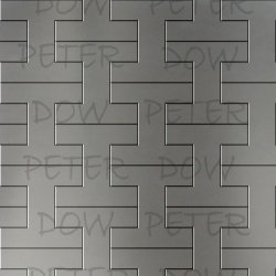
From the engineering consideration that regular tiles and bricks are far from optimal in terms of adding strength to structures, I've been considering that better would be this very particular 2D pattern of tiles and bricks illustrated in this image which I first posted in a topic in the USMB Arts & Crafts forum, Tessellated I - my simple technical drawing, coloured artfully

View larger version of Tessellated I in Steel 1800 x 800
Representing a surface of "I"-shaped (rotated by 90 degrees, "H"-shaped) steel tiles. The shape is of square proportions, the column of the I being one third of the width of the square and the top and the base one quarter of the height of the square.
Here is an I-tessellation in paving stones -

But my pattern of I or H tiles or bricks is very specifically designed so that it can be developed into a more detailed 3-D design which introduces further efficient tile-to-tile / brick-to-brick interlocking or making-rigid features which solve some of the limitations and issues arising with structures made from conventional bricks and tiles.
Conventional brickwork structures need a weaker mortar layer to hold a brick wall together -

Conventional tiled structures need to stick tiles onto a mounting surface -

These limitations of those brick-to-brick or tile-to-tile bonding methods make for weaker and heavier brick and tile structures than is ideal in some engineering applications.
In particular for temporary brick or tile structures, a high strength to weight ratio is desirable so that the parts of the structure can be moved easily to where they need to be erected.
In addition, temporary structures need the ability to disassemble the structure as easily as it was assembled.
We see examples of ease of disassembling a structure with kids building toys such as Lego and Meccano and in many manufactured products which use such typical features as nuts and bolts and bolt-holes but many other variations to secure one part to another strongly but in a reversible and flexible way.

So with those requirements in mind, my 2D I / H tessellation pattern was designed with a view to a 3D design of structures which I will now specify and show you a model to help me explain my 3D design more clearly.
3-Dimensional model video


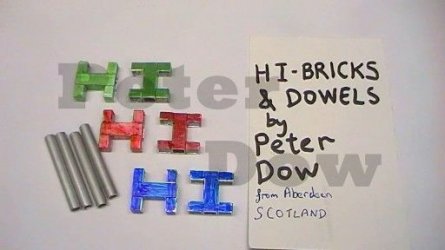
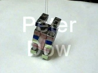
VIDEO - Tessellated I or H bricks and tiles for stronger, lighter assembled structures (YouTube)
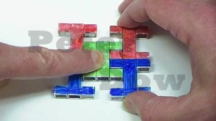
This video shows my model of the 3-dimensional shape of a simple structure composed of 6 bricks or tiles, each of which, when viewed from one-direction anyway, is a 2-dimensional "I"-shape (equally when rotated by 90 degrees "H"-shaped).
This model has been made from aluminium tubing and in order to distinguish one brick from another they have been coloured using marker pens - so there are two bricks coloured blue, two coloured green and two coloured red. This colouring was necessary for clarity because otherwise the permanent joints within bricks (which are only an artifact of the method to make a brick from square tubing) might be confused with the simple touching surface where two neighbouring bricks abut, abutting securely but without being in any way stuck by glue etc.
This 3-Dimensional model reveals a further design feature of the I or H brick and tile structures, which secures the bricks and tiles together in 2 further dimensions, some such feature being necessary because the 2-D I or H shape in of itself only secures the bricks together in 1 dimension.
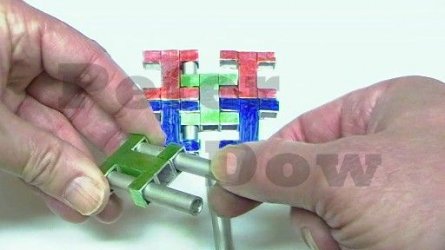
This feature is revealed here to be nothing more complicated than dowels or fixing rods which run in the vertical direction of the Is (or the horizontal direction of the Hs) through shafts in the Is' bases and tops and which serve to lock the tops and bases of neighbouring Is together, preventing movement radially from the dowels.
These dowels may henceforth be referred to as "Mazurka Dowels" named after the username of a scientist in an internet science forum who first correctly anticipated this feature of my 3-D design and its function to hold the structure together in all 3-dimensions, in a reply post to my topic there describing in detail only the 2-D tessellation, suggesting somewhat vaguely that some such design element was required for a good 3-D design with a view to seeing who would suggest the solution I had thought of first.
As I explained in that topic I could hardly call those dowels the "Dow dowels" there being too many dows in that name and anyway, my name can be used to reference this particular shape of I or H tile and brick and structures composed of them, as per "Dow tile" "Dow brick" "Dow I-tile" "Dow H-brick" "Dow I-H-brick" "Dow I-H-brick structure" "Dow I-structure" etc.
View larger version of Tessellated I in Steel 1800 x 800
Representing a surface of "I"-shaped (rotated by 90 degrees, "H"-shaped) steel tiles. The shape is of square proportions, the column of the I being one third of the width of the square and the top and the base one quarter of the height of the square.
Here is an I-tessellation in paving stones -
But my pattern of I or H tiles or bricks is very specifically designed so that it can be developed into a more detailed 3-D design which introduces further efficient tile-to-tile / brick-to-brick interlocking or making-rigid features which solve some of the limitations and issues arising with structures made from conventional bricks and tiles.
Conventional brickwork structures need a weaker mortar layer to hold a brick wall together -
Conventional tiled structures need to stick tiles onto a mounting surface -
These limitations of those brick-to-brick or tile-to-tile bonding methods make for weaker and heavier brick and tile structures than is ideal in some engineering applications.
In particular for temporary brick or tile structures, a high strength to weight ratio is desirable so that the parts of the structure can be moved easily to where they need to be erected.
In addition, temporary structures need the ability to disassemble the structure as easily as it was assembled.
We see examples of ease of disassembling a structure with kids building toys such as Lego and Meccano and in many manufactured products which use such typical features as nuts and bolts and bolt-holes but many other variations to secure one part to another strongly but in a reversible and flexible way.
So with those requirements in mind, my 2D I / H tessellation pattern was designed with a view to a 3D design of structures which I will now specify and show you a model to help me explain my 3D design more clearly.
3-Dimensional model video
VIDEO - Tessellated I or H bricks and tiles for stronger, lighter assembled structures (YouTube)
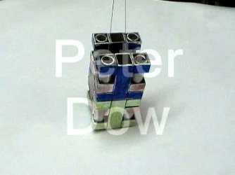
This video shows my model of the 3-dimensional shape of a simple structure composed of 6 bricks or tiles, each of which, when viewed from one-direction anyway, is a 2-dimensional "I"-shape (equally when rotated by 90 degrees "H"-shaped).
This model has been made from aluminium tubing and in order to distinguish one brick from another they have been coloured using marker pens - so there are two bricks coloured blue, two coloured green and two coloured red. This colouring was necessary for clarity because otherwise the permanent joints within bricks (which are only an artifact of the method to make a brick from square tubing) might be confused with the simple touching surface where two neighbouring bricks abut, abutting securely but without being in any way stuck by glue etc.
This 3-Dimensional model reveals a further design feature of the I or H brick and tile structures, which secures the bricks and tiles together in 2 further dimensions, some such feature being necessary because the 2-D I or H shape in of itself only secures the bricks together in 1 dimension.
This feature is revealed here to be nothing more complicated than dowels or fixing rods which run in the vertical direction of the Is (or the horizontal direction of the Hs) through shafts in the Is' bases and tops and which serve to lock the tops and bases of neighbouring Is together, preventing movement radially from the dowels.
These dowels may henceforth be referred to as "Mazurka Dowels" named after the username of a scientist in an internet science forum who first correctly anticipated this feature of my 3-D design and its function to hold the structure together in all 3-dimensions, in a reply post to my topic there describing in detail only the 2-D tessellation, suggesting somewhat vaguely that some such design element was required for a good 3-D design with a view to seeing who would suggest the solution I had thought of first.
As I explained in that topic I could hardly call those dowels the "Dow dowels" there being too many dows in that name and anyway, my name can be used to reference this particular shape of I or H tile and brick and structures composed of them, as per "Dow tile" "Dow brick" "Dow I-tile" "Dow H-brick" "Dow I-H-brick" "Dow I-H-brick structure" "Dow I-structure" etc.
Attachments
Last edited by a moderator: