Peter Dow
Freedom lover & fighter

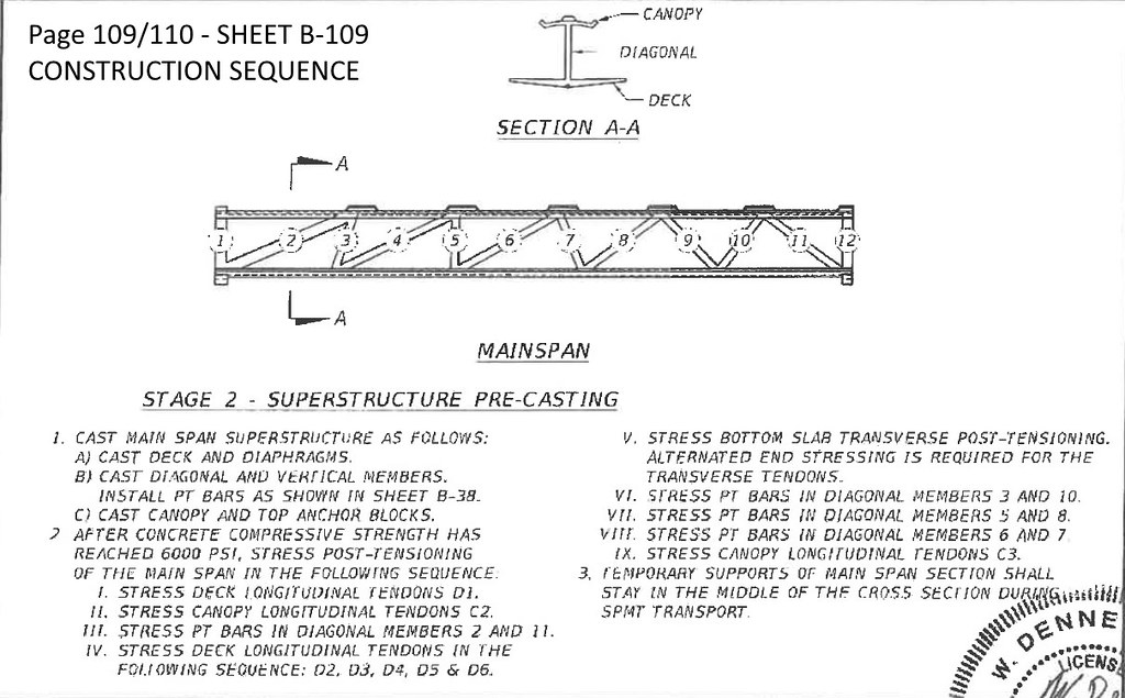
<- North ----------------------------------------------------------------------------------------------------- South ->
Experts cite explosive joint failure as cause of Florida bridge collapse
“I think they probably were carrying out jacking works,” said Bourne. “You only have a jack connected to the bar on for the few minutes you’re stressing and it’s still on in the collapsed condition. If they weren’t stressing it, it wouldn’t be there.”
It is this additional force being put into the diagonal member during the jacking operation that Bourne thinks could have caused failure of the critical end joint.
<- South ------------------------------------------------------------------------------------------------------------------ North ->
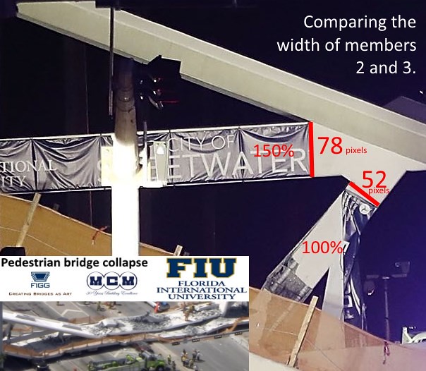
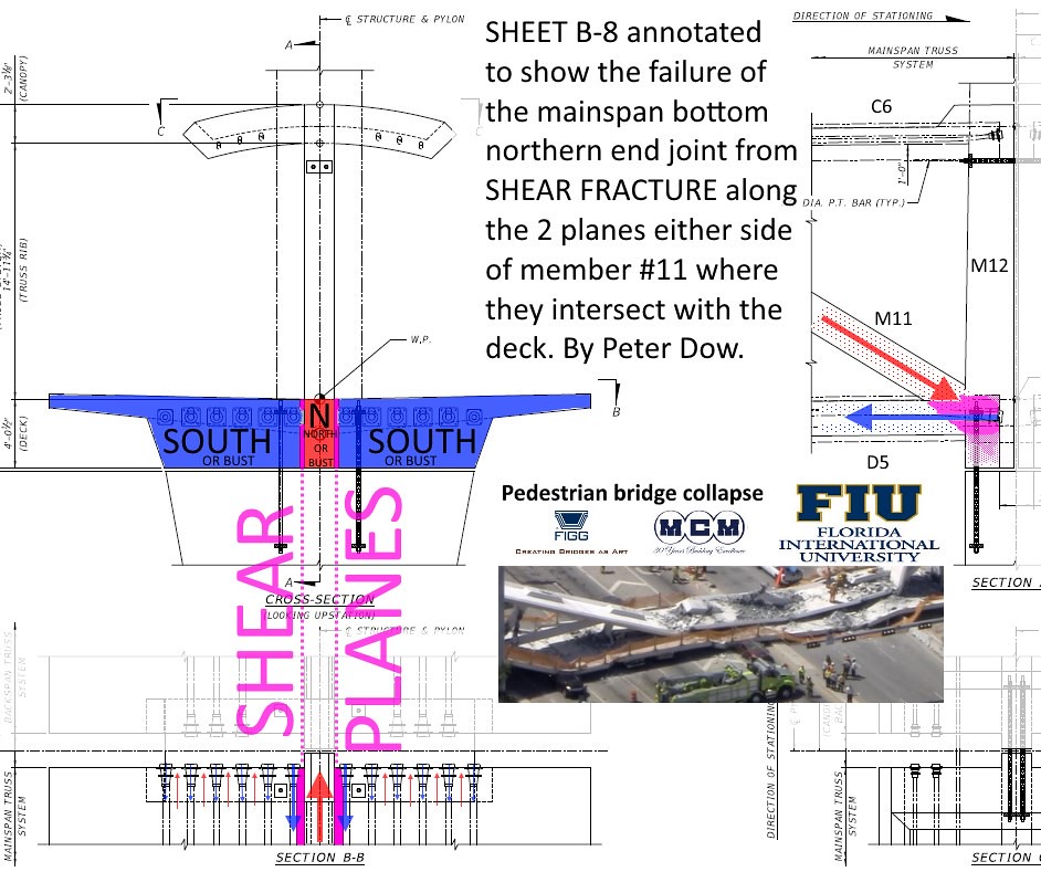
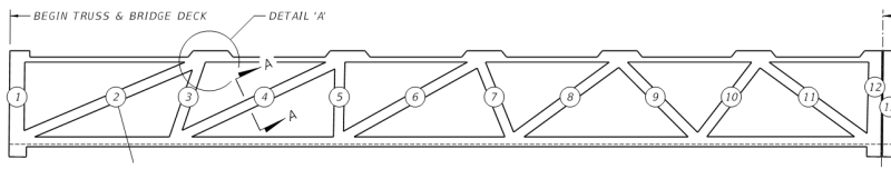
Damage to the side of truss member #11 is spalling caused by the explosive release of elastic energy which was stored in the highly stressed post-tensioning bar within when it snapped.
This, along with the picture of the jack still attached to the P.T. bar, is the smoking gun.


Forensic engineering conclusion
There is no satisfactory way to "implement" a house of cards. It is an intrinsically precarious structure.

Maybe somewhere there is a house of cards which has stood the test of time, but it is generally understood that the metaphorical reference to a "house of cards" is to compare it with something that is precarious, unstable and prone to failure - in this case the FIU pedestrian bridge.
If, as it seems the evidence may be pointing to, the bridge failed because of what one worker did in a minute dangling from crane with a jack to a P.T Bar then that proves that the bridge was precarious and so it had a bad design.
A good design should exclude the possibility for one worker doing something inept, whether under orders to do that something inept or not, which causes the collapse of the whole structure.
A good design would build in redundancy so that if one component failed - like a P.T. bar or a truss member or a truss joint - then other P.T. bars or truss members or joints would save the bridge.
Or a good design would use a truss made from rigid metal-only members (tubes or girders) and metal-only joints and avoided the problems of trusses made from prestressed or post-tensioned concrete on such a critical component of a bridge.
Political questions
The FIU bridge collapse story was reported by the BBC in Britain and world-wide and that's how the story came to my attention. FIU claims to be an "International" university - an invitation (or at least an excuse) for discussion of FIU's affairs on the world wide web, maybe?
Public Safety
A pedestrian underpass would have been safer and cheaper than a bridge, right? So public safety and cost was not the top priority. Is that acceptable?
Management
The bridge project was mismanaged to the point of killing people. Are there wider problems which this tragedy highlights - problems with mismanagement of this university, other universities, civil engineering management at this site or elsewhere?
Legal
Florida Involuntary Manslaughter Laws
Overview of Florida Involuntary Manslaughter Laws
When a homicide, the killing of a human being, does not meet the legal definition of murder, Florida state laws allow a prosecutor to consider a manslaughter charge. The state establishes two types of manslaughter: voluntary and involuntary. While voluntary manslaughter describes an intentional act performed during a provocation or heat of passion, involuntary manslaughter does not require intent to kill or even intent to perform that act resulting in the victim's death.
To establish involuntary manslaughter, the prosecutor must show that the defendant acted with "culpable negligence." Florida statutes define culpable negligence as a disregard for human life while engaging in wanton or reckless behavior. The state may be able to prove involuntary manslaughter by showing the defendant's recklessness or lack of care when handling a dangerous instrument or weapon, or while engaging in a range of other activities that could lead to death if performed recklessly.
Who are the individuals responsible for the loss of life and are they criminally culpable with regard to the decisions they made negligently or recklessly that disregarded the dangers to human life and contributed to the deaths?
Civil liability. Who should pay compensation and how much?
Political
Who is to blame politically, Obama or Trump or neither? Will anyone be held politically accountable for these deaths?